|
Pipe2CAD 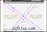
|
Pipe2CAD is an AutoCAD add-on freeware that can be used efficiently to complete the design work of pipe networks, such as water supply, sanitary sewer, and storm drainage networks.
After finishing the hydraulic design of your pipe networks with any of the available hydraulic design packages, networks can be easily imported into Pipe2CAD environment to proceed with all subsequent design steps. From checking interference points and conflict between different networks, verification of low and high points in pressure networks, and editing networks by adding, deleting, or adjusting pipes; to finally producing fully formatted plan views and longitudinal profiles, ready for submission!
Pipe2CAD Features
1. Importing Pipe Networks
Pipe2CAD has a very powerful importing module that is able to import pipe network data from almost any hydraulic modeling application. Pipe network data can be imported in the form of text files containing data of pipes and nodes, or through Shapefiles which can be produced by a wide range of pipe network design programs. Also Pipe2CAD can directly read the EPANET files and EPA SWMM files (*.inp), which are industry standards for water distribution and storm water models.
Because the produced network data from hydraulic design programs are not always in the same form, Pipe2CAD can complete any missing part of the imported network data. It can even calculate the invert levels of pipes based on the criteria you define for this.
2. Exporting Pipe Networks
Like in the importing module, Pipe2CAD can export pipe network data in two formats, which are shapefiles and text files. By using the exporting feature, you can get your data back to the hydraulic design application after implementing changes for further check. Exporting shapefiles enables you to transfer your network data to a GIS environment to be employed in mapping process; while exported text files can be opened with a spreadsheet program to carry out quantity calculations.
3. Editing Environment
Pipe2CAD works as a fully dynamic engineering model, for example if you adjust the invert level of a pipe, all related pipe annotations, node annotations, crossing points are automatically adjusted. This dynamic environment greatly reduces design mistakes, and saves much time and effort.
Several editing features help you to apply modifications to the model quickly and accurately. With a double click on a pipe or a node, you can edit all of its data. You have a Group Editing feature that allows you to apply a similar change to several elements same time. Other common edits are available also like splitting a pipe into two pipes, merging several pipes into one, and reversing a pipe direction. If you run Pipe2CAD on AutoCAD Civil 3D, you gain one more feature for capturing ground levels at nodes from a surface.
4. Crossing Points/Pipe Interference
The most exciting part of Pipe2CAD is its way in treating the pipe interference issue. From the first moment you import a network or create a new one, all crossing points of this network with all other networks are automatically analyzed. The results of this analysis appear in the form of crossing point annotations on the drawing. At every intersection between two pipes of two different networks, an annotation is placed showing the diameters and invert levels of the two pipes, and the vertical clearance between them. While you are editing the networks, these crossing annotations are automatically updated.
When you have several networks in your project these annotations can make a big mess. Using crossing points options, you can select to show or hide all of them, or instead decide which of them to see. For example, if you have four networks A, B, C, and D; you may ask Pipe2CAD to show only crossing points of network A with C, and B with D. You can be more specific and make it show only crossing points where clearance between pipes is less than 1 ft.
5. Low and High Points of pressure networks
Defining low points and high points of pressurized water networks (like water distribution, irrigation, and fire fighting networks) is a vital part of good design. When you import or create a new pressure network, Pipe2CAD automatically marks low points with red circles, and high points with green circles. While you are editing the network, low and high points are automatically re-analyzed and updated.
6. Longitudinal Profiles
With Pipe2CAD you can produce fully formatted longitudinal profiles of pipelines in few seconds. Profile styles give you the ability to define the contents and format of the generated profiles. You decide which data bands to appear and how it will look. Profile styles also can be exported and imported in the form of text files, so when you define a standard style you can distribute it to the whole project team, or may be to the whole department.
A Longitudinal profile of a pipeline can show the crossing pipes of other networks passing above or below it. All crossing pipes are shown with full data (network name, size, and invert level). Using this vital feature with the crossing point annotations on plan, you can easily make fast and accurate judgment on pipe interferences.
Long length profiles can be automatically split into several parts with a predefined maximum length, so that no manual post-processing is needed on the produced profiles.
The license of this software is Freeware, you can free download and free use this cad software.