|
Micrometer Model 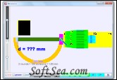
|
Analyze a micrometer with this tool. The Micrometer Model shows the principle of operation and the physical parts of a real micrometer.?Micrometers use a screw to amplify distances that are too small to measure directly into large rotations of the screw that are big enough to read from a scale. The accuracy of a micrometer derives from the accuracy of the thread that is at its heart. The basic operating principles of a micrometer is that the rotation of an accurately made screw can be directly and precisely correlated to a certain amount of axial movement (and vice-versa), through the constant known as the screw's lead. A screw's lead is the distance it moves forward axially with one complete turn (360. (In most threads [that is, in all single-start threads], lead and pitch refer to essentially the same concept.) With an appropriate lead and major diameter of the screw, a given amount of axial movement will be amplified in the resulting circumferential movement.
Micrometer Frame (Orange) The C-shaped body that holds the anvil and barrel in constant relation to each other. It is thick because it needs to minimize expansion, and contraction, which would distort the measurement. The frame is heavy and consequently has a high thermal mass, to prevent substantial heating up by the holding hand/fingers. has a text 0.01 mm for smallest division of instrument has a text 2 rounds = 100 = 1.00 mm to allow association to actual micrometer
1. Anvil (Gray) The shiny part that the spindle moves toward, and that the sample rests against.
2. Sleeve / barrel / stock (Yellow) The stationary round part with the linear scale on it. Sometimes vernier markings.
3. Lock nut / lock-ring / thimble lock (Blue) The knurled part (or lever) that one can tighten to hold the spindle stationary, such as when momentarily holding a measurement.
4. Screw (not seen) The heart of the micrometer It is inside the barrel.
5. Spindle (Dark Green) The shiny cylindrical part that the thimble causes to move toward the anvil. The green slider in the bottom panel controls the position of the spindle.
6. Thimble (Green) The part that one's thumb turns. Graduated markings.
7. Ratchet (Teal) (not active in simulation) Device on end of handle that limits applied pressure by slipping at a calibrated torque.
The Micrometer model has an object (Black) with slider on left top to control the y-motion of the object into the anvil and spindle (jaws), the graphics also allows drag action. with slider on left bottom to control the x-size of the object into the anvil and spindle (jaws).
On the left bottom slider is the zero error control to allow of exploring with if the micrometer has either +0.15 mm (max) or -0.15mm (min) zero error.
The reset button restores the Micrometer model to its default setting.
Requirements:
* Java
The license of this software is Free, you can free download and free use this graphing software.